While browsing the forums following the announcement of the Convergence of Cyriss, I saw a post comparing the Convergence designs to Lovecraftian architecture—lots of non-Euclidean shapes and curves that bend dimensions and inspire madness. My first thought was, “you have no idea . . .”
There are a lot of mind-bending challenges when it comes to converting the two-dimensional, swoopy curves and overlapping plates of the Convergence concept drawings into three-dimensional designs. Fortunately, concept artist Andrea Urdezo has done a fantastic job keeping his designs consistent, which has been immensely helpful in modeling these figures.
As with all the model-making I do, there are a few dozen ways to get from points A to B. In this blog I’ll go through the steps I used to digitally design some of the more basic plates and curves. To kick things off, I’ll show you how I built the blade shields for one of the heavy vectors:
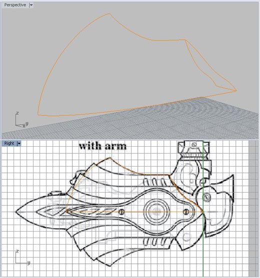
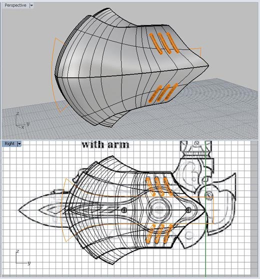
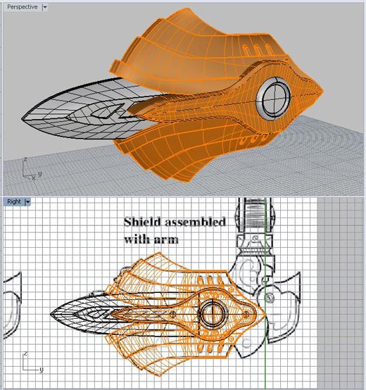
In this image I dropped the side-view of the blade shield into the background of the 3D program and drew half the curves that make up its shape.
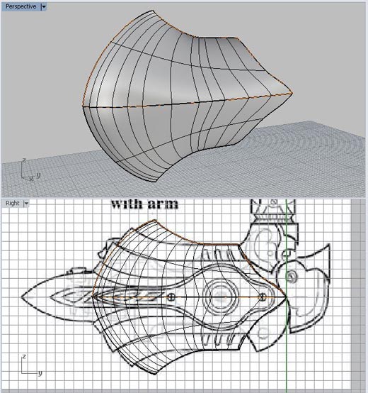
I filled the curves with a surface, then mirrored it vertically and filled in all the surfaces on the back.
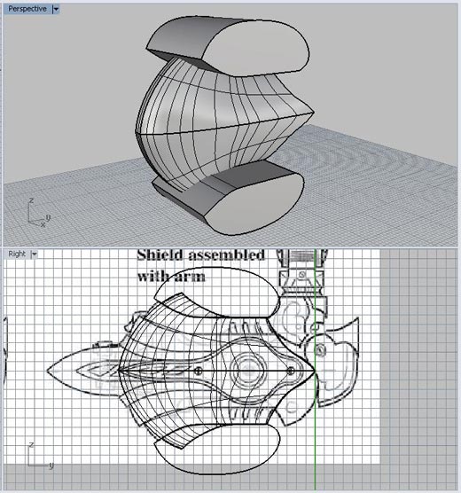
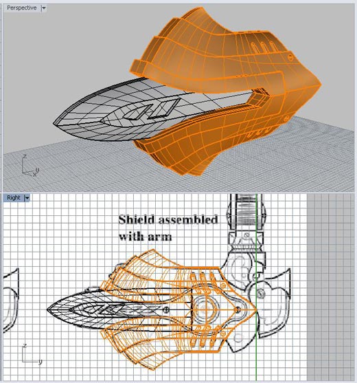
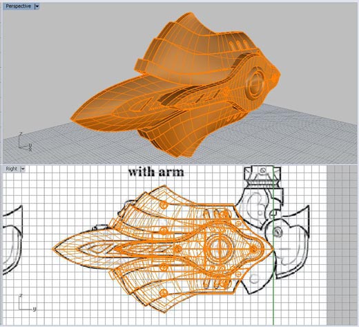
I selected and copied the shape, then drew and extruded shapes to subtract from the current piece.
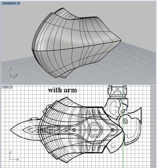
Here I cut the main plate with the extruded shape, scaled it up, and pasted the original plate back into the model.
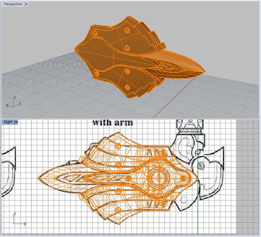
I drew and projected lines for the vents. Then I createed pipes around the curves and subtracted them from the plate.
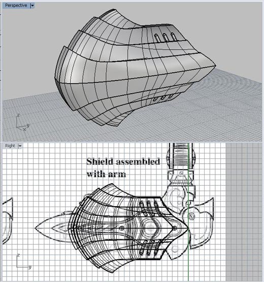
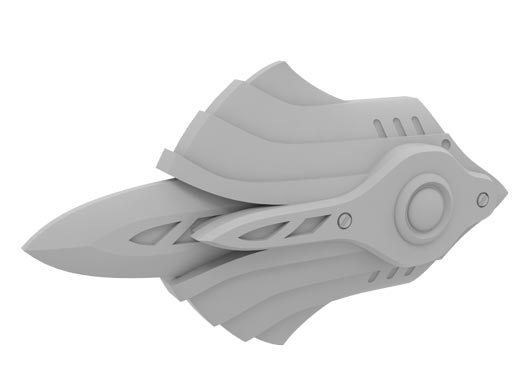
I repeated the copy, paste, and subtract process for the next two plates.
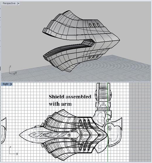
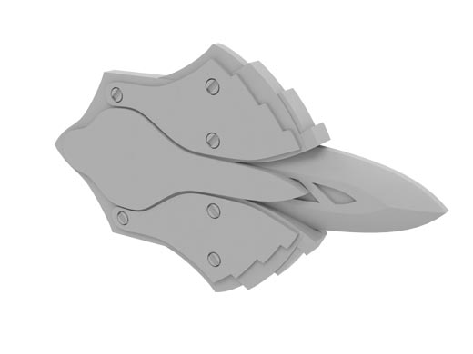
Pictured here, I extruded and cut a notch for the blade.
Here I drew curves, created planes, and cut blade details.
Then I drew curves, created planes, and revolved the top-most plate detail.
I cut screw details and added disc shapes to the top plate.
Finally I added back plates and screw details.
Keep an eye out for my next blog, where I’ll tackle something even more challenging.
–Ben Misenar